| 690.4 |
Installation |
(F) Circuit Routing. Photovoltaic source and PV output conductors, in and out conduit, and inside of building or structure, shall be routed along with building structural members such as beams, rafters, trusses, and columns where the location of those structural members can be determined by observation. Where circuits are embedded in built-up, laminated, or membrane roofing materials in roof areas not covered by PV modules or associated equipment, the circuits’ location shall me clearly marked. |
| 690.5 |
Ground Fault Protection |
(C) Labels and Markings. A solar warning label shall appear on the utility-interactive inverter or be applied by the installer near the ground-fault at a visible location, stating the following: “WARNING ELECTRIC SHOCK HAZARD IF GROUND FAULT IS INDICATED, NORMALLY GROUNDED CONDUCTORS MAY BE UNDERGROUND AND ENERGIZED.” When the photovoltaic system also has batteries in a visible location at the batteries. |
| 690.7(E)(3) |
Bipolar Source and Output Circuits |
For 2-wire circuits connected to bipolar systems, the maximum system voltage shall be the highest voltage between the conductors of the 2-wire circuit if all of the following conditions apply_ (3) The equipment is clearly marked with a label as follows: “WARNING BIPOLAR PHOTOVOLTAIC ARRAY, DISCONNECTION OF NEUTRAL OR GROUNDED CONDUCTORS MAY RESULT IN OVERVOLTAGE ON AN ARRAY OR INVERTER.” |
| 690.10(C) |
Stand Alone System |
(C) Single 120 volt supply: The inverter output of a standalone solar photovoltaic system shall be permitted to supply 120 volts to a single-phase, 3-wire, 120/240-volt service equipment or distribution panels where there are no multi-wire branch circuits in all installations, the rating of the overcurrent device connected to the output of the inverter shall be less than the rating of the neutral bus in the service equipment. The equipment shall be marked with the following words or equivalents: “WARNING SINGLE 120-VOLT SUPPLY, DO NOT CONNECT MULTIWIRE BRANCH CIRCUITS!” |
| 690.14(C)(2) |
Requirement For Disconnection Means |
(2) Markings. Each photovoltaic system disconnecting means shall be permanently marked to identify it as a photovoltaic system disconnect. |
| 690.15 |
Disconnection of Photovoltaic Equipment |
Means shall be provided to disconnect equipment, such as inverters, batteries, charge controllers, and the like from all underground conductors of all sources. If the equipment is energized from more than one source the disconnecting means shall be grounded and identified. |
| 690.16(B) |
Disconnecting Means |
(B) Fuse Servicing. Disconnecting means shall be installed on PV output circuits where overcurrent devices (fuses) must be serviced that cannot be isolated from energized circuits. The disconnecting means shall be within sight of, and accessible to the location of the fuse or integral with a fuse holder and shall comply with 690.17. Where the disconnecting means are located more than 1.8 m (6ft.) from the overcurrent devices, a directory showing the location of each disconnect shall be installed at the overcurrent device location. Non-load break rated disconnection means shall be marked “Do Not Open Under Load” |
| 690.17(4) |
Switch or Circuit Breaker |
(4) Having an interrupting rating sufficient for the nominal circuit voltage and the current that is available at the line terminals of the equipment. Where all terminals of the disconnecting means may be energized in the open position, a warning sign shall be mounted on or adjacent to the disconnecting means. The sign shall be clearly legible and have the following words or equivalent: “WARNING ELECTRIC SHOCK HAZARD. DO NOT TOUCH TERMINALS. TERMINALS ON BOTH THE LINE AND LOAD SIDE MAY BE ENERGIZED IN THE OPEN POSITION.” Exception: A connector shall be permitted to be used as an AC or DC disconnecting means provided that it complies with the requirements of 690.33 and is listed and identified for the use. |
| 690.31(E)(3) |
Direct Current Photovoltaic Source and Output Circuits |
(3) Marking or Labeling Required. The following wiring method and enclosures that contain PV power source conductors shall be marked with the wording “Photovoltaic Power Source” by means of permanently affixed labels or other approved permanent marking: (1) Exposed raceways, cable trays, and other wiring methods (2) Covers or enclosures of pull boxes and junction boxes (3) Conduit bodies in which any of the available conduit openings are unused. |
| 690.31(E)(4) |
Direct-Current Photovoltaic Source and Output Circuits Inside a Building |
(4) Marking or Labeling Methods and Locations. The labels or markings shall be visible after installation. Photovoltaic power circuit labels shall appear on every section of the wiring system that is separated by enclosures, walls, partitions, celling’s or floors. Spacing between labels or markings or between a label and a marking shall not be more than 3 m (10ft.) Labels required by this section shall be suitable for the environment where they are installed. |
| 690.33(E)(2) |
Connectors |
(E) Interruption of Circuit. Connectors shall be either (1) or (2): (1) Be rated for interrupting current without hazard to the operator. (2) Be a type that requires the use of a tool to open and marked “Do Not Disconnect Under Load” or “Not For Current Interrupting” |
| 690.35(F) |
Underground Photovoltaic Power System |
(F) The photovoltaic power source shall be labeled with the following warning at each junction box, combiner box, disconnect and device where energized, underground circuits may be exposed during service: “WARNING ELECTRIC SHOCK HAZARD. THE DC CONDUCTOR OF THIS PHOTOVOLTAIC SYSTEM ARE UNDERGROUND AND MAY BE ENERGIZED” |
| 690.53(D) |
Direct-Current Photovoltaic Power Source |
A permanent label for the direct-current photovoltaic power source indicating items (1) through (5) shall be provided by the installer at the photovoltaic disconnecting means: (1) Rated maximum power-point current (2) Rated maximum power-point voltage (3) Maximum system voltage informational Note to (4) Short circuit current. See 690.8 (A) for calculation of maximum circuit current (5) Maximum rated output current of the charge controller (if installed) informational Note: Reflecting systems used for irradiance enhancement may result in increased levels of output current and power. |
| 690.54 |
Interactive System Point of Interconnection |
All interactive system(s) points of interconnection with other sources shall be marked at an accessible location at the disconnecting means as a power source and with the rated AC output current and the nominal operating AC voltage. |
| 690.55 |
Photovoltaic Power Systems Employing Energy Storage |
Photovoltaic Power Systems Employing Energy Storage Photovoltaic power systems employing energy storage shall also be marked with the maximum operating voltage including any equalization voltage and the polarity of the grounded circuit conductor. |
| 690.56(A) |
Identification of Power Sources |
(A) Facilities with Stand-Alone Systems. Any structure or building with a photovoltaic power system that is not connected to a utility service source and is a stand-alone system shall have a permanent plaque or directory installed on the exterior of the building or structure at a readily visible location acceptable to the authority having jurisdiction. The plaque or directory shall indicate the location of the system disconnecting means and that the structure contains a stand-alone electrical power system. |
| 690.56(B) |
Identification of Power Sources |
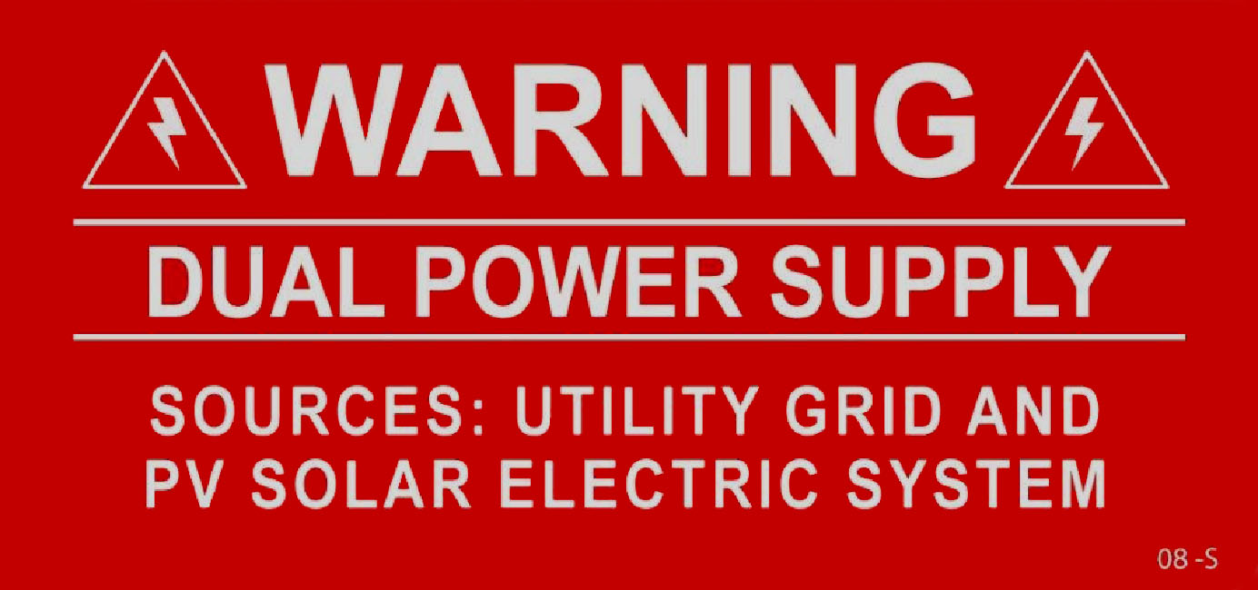
(B) Facilities with Utility Services and PV Systems. Buildings or structures with both utility service and the photovoltaic system shall have a permanent plaque or directory providing the location of the service disconnecting means and the photovoltaic system disconnecting means if not located at the same location. |
| 705.12(3)(4) |
Utility-Interactive Inverters |
(4) Markings. Equipment containing overcurrent devices in circuits supplying power to a bus bar or conductor supplied from multiple sources shall be marked to indicate the presence of all sources. |
| 705.12(D)(7) |
Utility-Interactive Inverters |
(7) Inverter Output Connections. Unless the panel board is rated not less than the sum of the ampere ratings of all overcurrent devices supplying it, a connection in a panel board shall be positioned at the opposite (load) end from the input feeder location or main circuit location. The bus or conductor rating shall be sized for the loads connected in accordance with Article 220. In systems with panel boards connected in series, the rating of the first overcurrent device directly connected to the output of a utility-interactive inverter(s) shall be used in the calculations for all bus bars and conductors. A permanent warning label shall be applied to the distribution equipment with the following or equivalent wording: “WARNING INVERTER OUTPUT CONNECTION DO NOT RELOCATE THIS OVERCURRENT DEVICE” |